
Configuration
500 kWth Atmospheric Pulverised Fuel Combustion Rig
Overview Combustion Facility
- Geometry: Vertically fired furnace
- Thermal input: 200 - 500 kW
- Inner diameter: 0.75 m / 0.85 m
- Furnace length: 7 m water cooled, upper 4 m additionally refractory lined
- Burner: Combi-burner natural gas/coal/pulverized fuel
- Primary and secondary air optionally swirled (by moveable block)
Fuel Treatment
- Capacity: 30 - 120 kg/h (depends on fuel)
- Hammer mill
- Impact mill with classifier (hard coal)
- Beater-wheel mill (brown coal)
- Blending and dosing-unit (max. 4 different fuels/additives)
- Fluidized bed dosing with rotating disc
Fuels
- Hard coal / Lignite / Peat / Natural Gas
- Straw / Wood / Bark / Energy Crops / Legumes
- Sewage sludge / RDF / Shredder Light Fraction
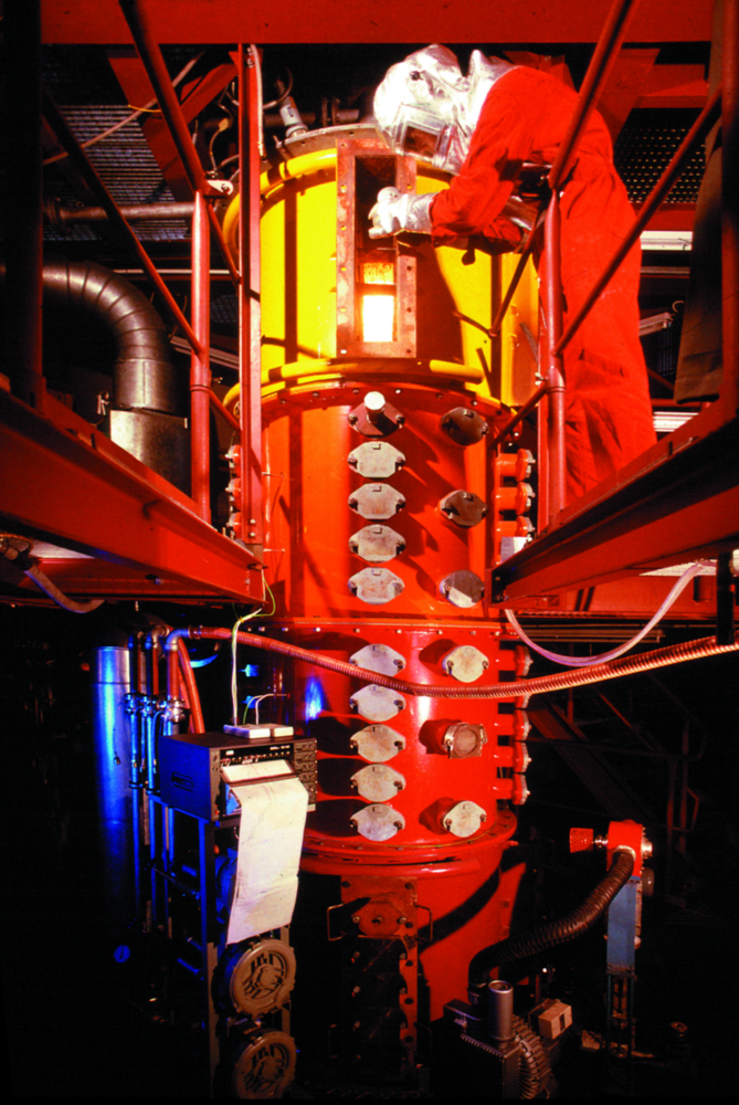
Side view combustion chamber
The combustion chamber is laid out symmetrically and is easily accessible from all sides realised by flanges at each 90°.
For staging purposes air and fuel are easily added by use of the flanges. Temperature profiles and gas analyses are also determined through the openings in the combustion chamber wall.
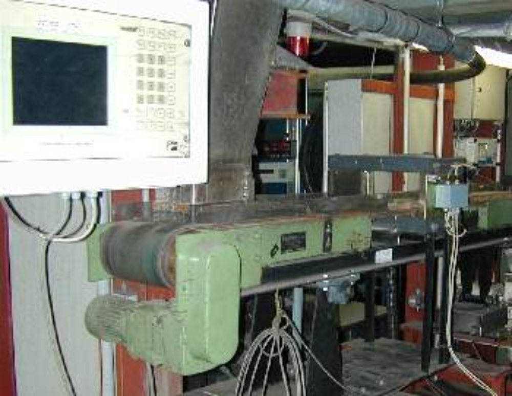
Belt weigher and metal detector
Direct dosing of brown coal is realised with the belt weigher.
All fuels to be milled are screened by the metal detector to prevent metals from entering the mill. By separating the metal fraction the mills are protected from destruction and flying sparks which otherwise could ignite the fuel milled.
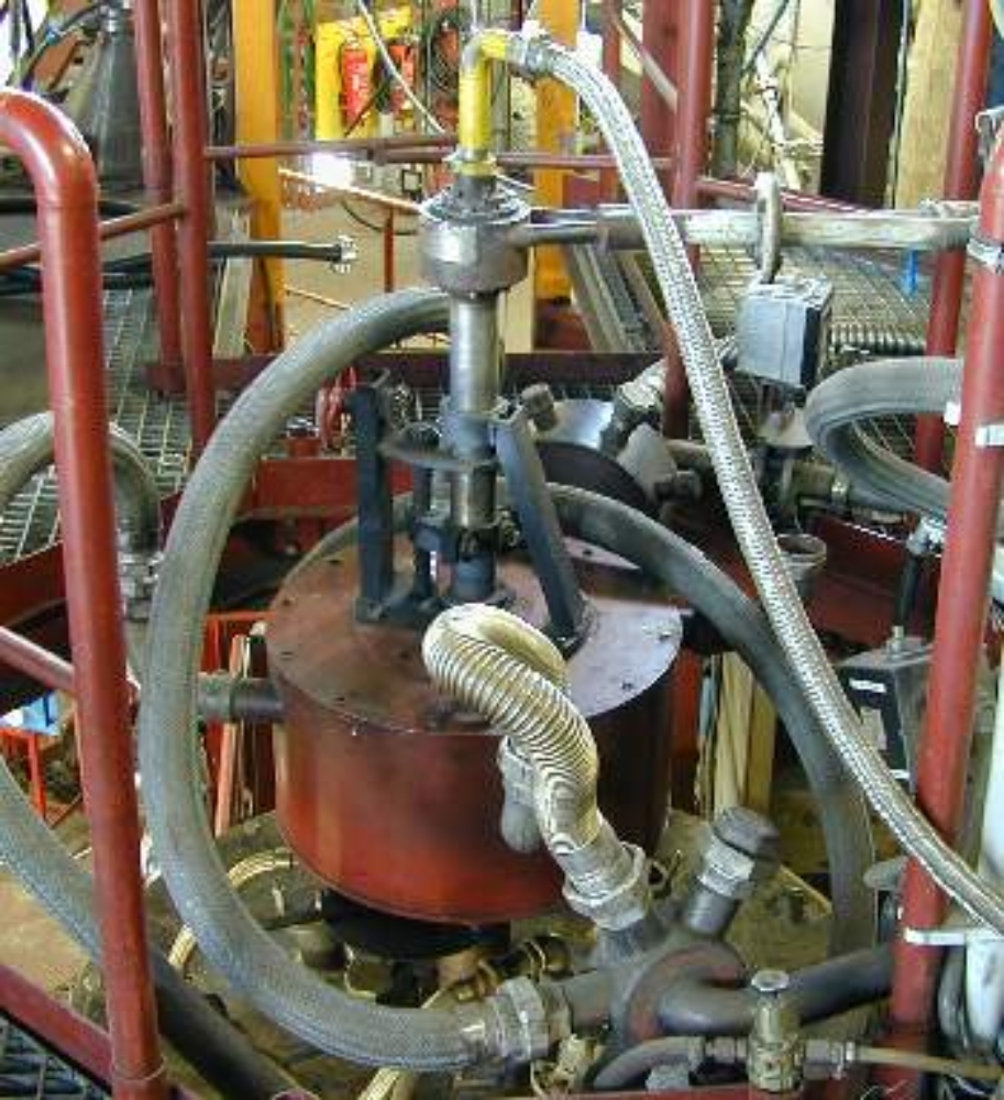
Burner pulverised fuel combustion rig
View of the burner including the moveable block (red cylinder) and attached secondary air hoses. In the upper right corner hoses of fuel and primary air.

Hammer mill plus mesh bottom
The open hammer mill with its beater are seen on the right side.
On the left a mesh bottom is seen. Depending on the mesh size, the circumferential velocity of the beater and the distance between beater and mesh bottom different mean diameters of the fuel to be milled are achieved.
Contact

Jörg Maier
Dipl.-Ing.Head of Department Firing Systems (KWF)